Gaggia Classic LED Water Tank Mod
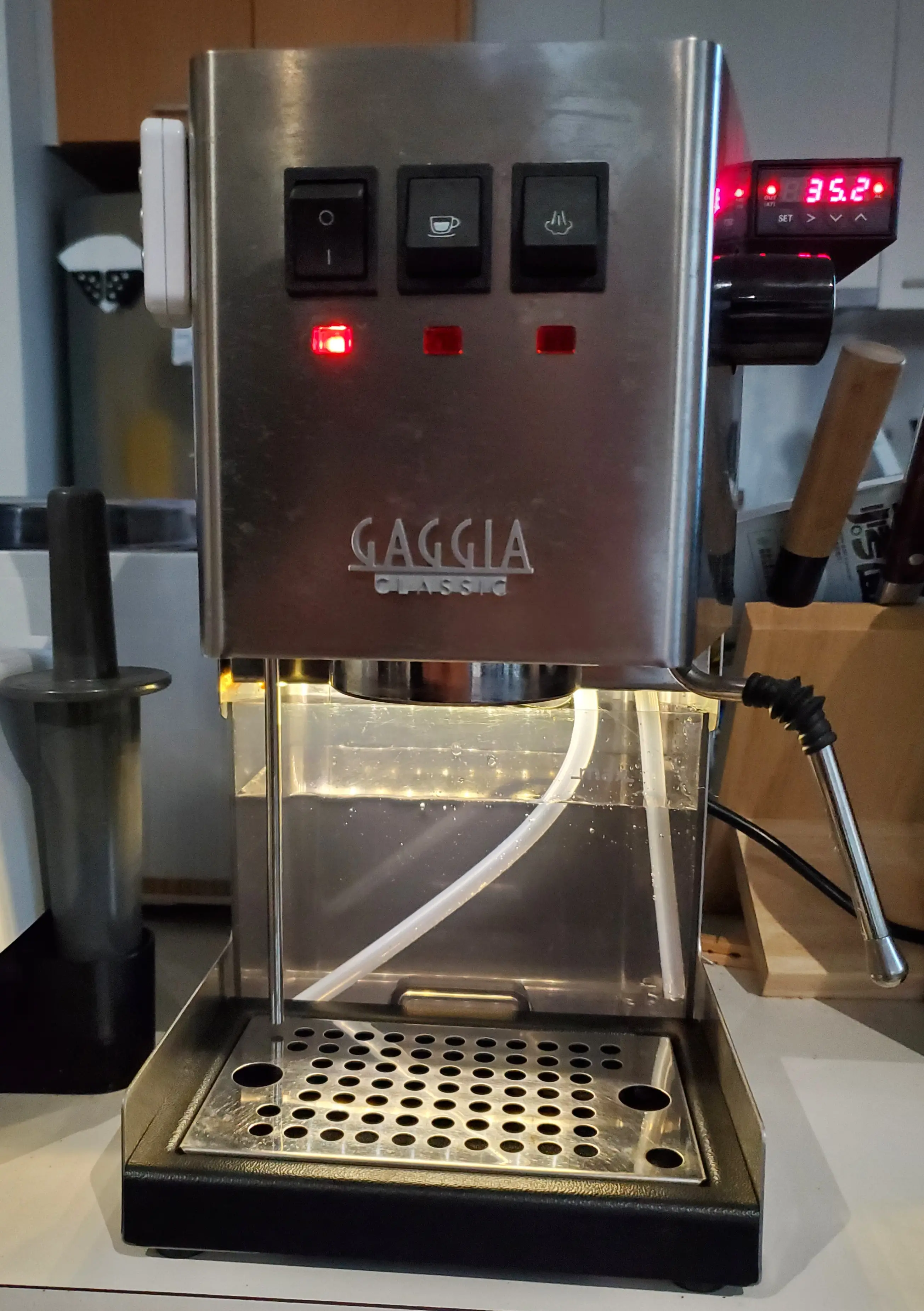
Since I bought the Gaggia Classic, one of the things which has always bugged me about it is how dimly lit the water tank is. A fairly common mod is to install an LED strip above the water tank, however unlike something like the PID mod guides are a little bit sparse.
Edit 2023-02-28: I ended up removing this mod. The power supply I had was way too overpowered, and lead to fairly sporadic temperature swings. I never ended up installing the smaller power supply.
I’m just about to start the Gaggiuino mod, where I’ll add a 5v LED strip. When I have a post about it you can read about it here.
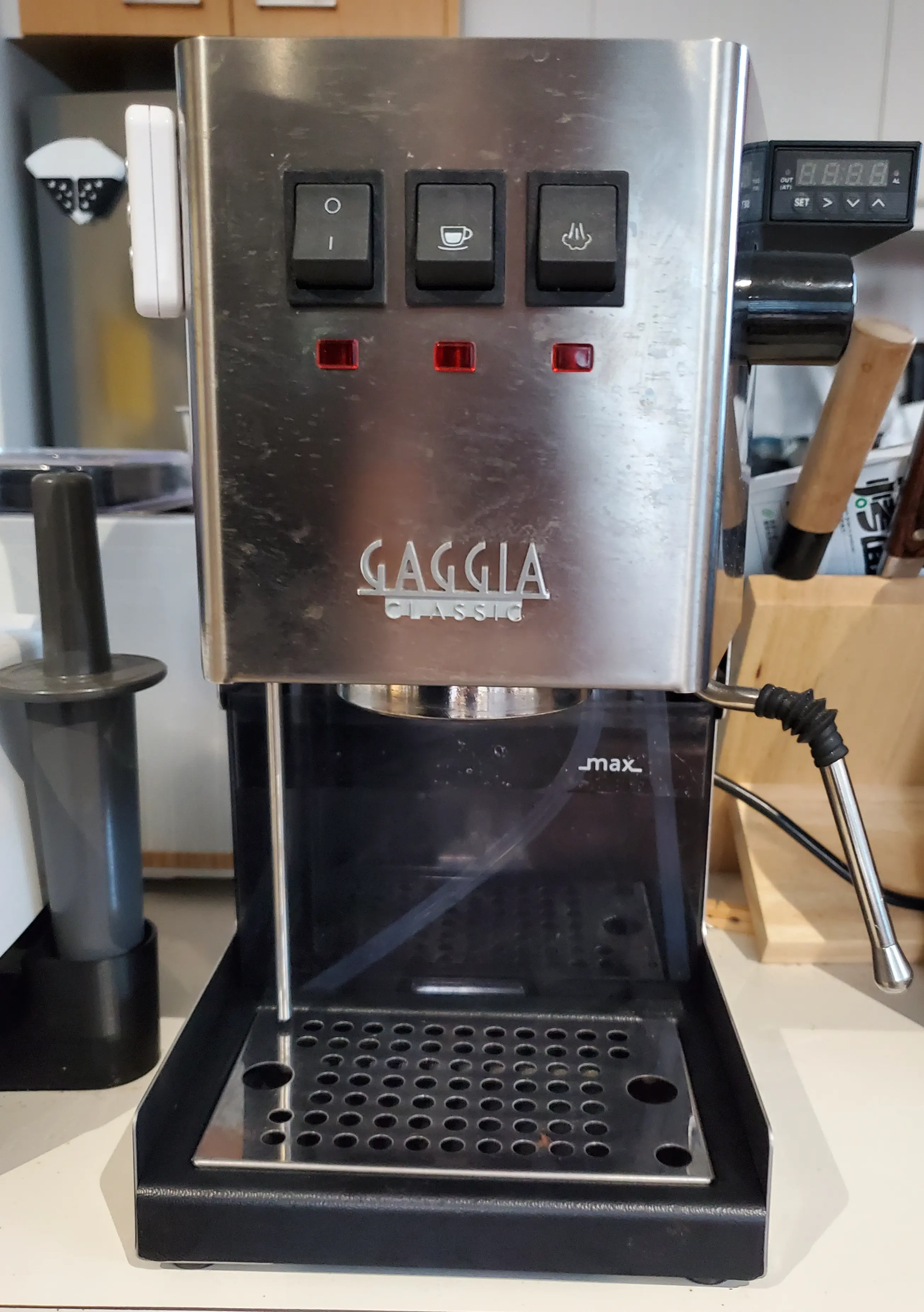
Without light to illuminate the water tank it’s quite difficult to determine the water level.
Before Getting Started
This involves mains power which if you’re not careful will kill you. Scrutinise every step, test every connection, test every connection with every switch combination. Please don’t blindly follow this guide.
If you’re not confident you can do this safely, talk to someone who can. Alternatively other options for seeing the water level include:
- Using your phones torch.
- Adding a brightly coloured straw to the tank.
The Guide
The wiring for the mod looks like the following:
          .------ EARTH ---------.
          |             _______  | ________
          |             |      | | |      |
          |    ______   |    __|_|_|__    |
          |   /     |   N    |       |    |
          |  |      |   E    |       |    A
          |  |      |   U    |  LED  |    C     __________
          .--. MAIN |   T    |       |    T     |        |
             |      |   R    |  PSU  |    I     | POWER  |
             |      |   A    |       |    V     | SWITCH |
              \_____|   L    |_______|    E     |________|
                 |      |      |   |      |       |
                 |______|      |   |      |_______|             _____________
                               |   |                            |           |
                               |   .--- POSITIVE ---------------.           |
                               |                                | LED STRIP |
                               .------- NEGATIVE ---------------.           |
                                                                |___________|
Parts
The following parts are required:
LED Lights: Warm White 60 LED, DC 12V, Waterproof IP65, 5m - Pay attention to the power requirements because that’s relevant for the next item.
LED Power Supply: 36W DC12V - This one is entirely overpowered, I’m going to replace it with a much smaller one, the wiring diagram will stay the same aside from the omission of an earth connection.
Piggy Back Connectors - These come in sets with various connectors. It’s probably a good idea to get one of those instead.
Heat Resistant Cable: 14 AWG
Additionally items like a multimeter, crimping tool, various crimping terminals (specifically male/female bullet terminals, or splice connectors).
Steps
-
Take the top off of the coffee machine, place the PSU inside, find a good place where it can fit, run the wires for the LED PSU output through the hole for the water funnel. Check that it can still close correctly, and that all the wires can reach their respective inlets/outlets.
-
Crimp the input ends of the LED PSU.
Wire Connection Active (Hot/Live/Line) Extend wire to power switch Earth (Ground) Piggyback Neutral Piggyback -
Crimp the output ends of the LED PSU.
Wire Connection Positive Female Bullet Negative Female Bullet -
Cut the LED strip to length.
-
Crimp the LED input ends.
Wire Connection Positive Male Bullet Negative Male Bullet -
Place the LED PSU in the coffee machine. Hook up the existing earth to the piggyback connector and the piggyback connector to the neutral prong on the inlet. Repeat the same for neutral wire.
MAINS (AS SEEN FROM INSIDE THE MACHINE) _________________ / | / .---------. | / | ACTIVE | | / .---------. | / | | | | | | .--------. | | | EARTH |---------(------------- EARTH --------------------. | .--------. | | | | | | | | \ | | \ .---------. | | \ | NEUTRAL |---(------------- NEUTRAL -------. | \ .---------. | | | \_________________| | | | | | | | | | | | | .-------- ACTIVE | | | | | | .---------.----------.----------.---------. | | | | | | | | | LED PSU INPUT | | | | | | | -
Connect the extended active wire to the power switch. To confirm the prong to use, run a continuity test with the active input, connect it to the one which completes when the continuity succeeds while switched on.
EARTH --------------------. POWER SWITCH (AS | SEEN FROM INSIDE | THE MACHINE) | .---------.---------. | | .---. | .---. | | | .---. | .---. | NEUTRAL -------. | .---------.---------. | | | .---. | .---. | | | | .---. | .---. | | | .---------.----|----. | | | | | | | | | | | .-------- ACTIVE ----------------------------. | | | | | | .---------.----------.----------.---------. | | | | | | | | | LED PSU INPUT | | | | | | | -
Connect the LED output wires to the LED strip.
| | | | | | | LED PSU OUTPUT | | | | | | | | | .------------.---------------.------------. | | | | .--------------------------------------------------------. | | | | | .----------- POSITIVE --------------. | | | .-. .-. .-. .-| | | LED STRIP | * | | * | | * | | *| | | '-' '-' '-' '-| .--------------------------- NEGATIVE --------------. | | | .--------------------------------------------------------. -
Adhere the LED strip to the ceiling of the water tank.
-
Done